Smartscope Project
Overview
Microscopy has been a cornerstone of scientific discovery for
centuries, enabling us to explore the hidden world of cells,
microorganisms, and intricate structures. However, traditional
microscopes can be expensive, bulky, and inaccessible to many,
which limits their accessibility - especially in remote or
resource-limited settings.
With the rapid advancement of smartphone technology, particularly
in camera resolution and processing power, there is an exciting
opportunity has emerged to make microscopy more accessible and
affordable by leveraging the capabilities of smartphones combined
with simple optical attachments to acheive magnification and imaging
of microscopic samples.
The smartscope project focused on designing and building a low-cost,
portable microscopy solution that can be easily attached to a smartphone.
The goal was to create a device that could provide sufficient
magnification and resolution to visualize microscopic samples
for basic scientific exploration, education purposes, and even field
diagnostics.
By integrating simple optical components with modetn smartphone
technology, the project demonstrated how accessible engineering
solutions can bridge the gap between advanced scientific tools and
everyday tecchnology.
Problems with Traditional microscopy
Some of the key challenges with traditional microscopy include:
- High-quality microscopes can be expensive, making them inaccessible to
many individuals, schools, local clinics in rural areas.
- Operating a microscope can require training and expertise, which can
be a barrier for non technical users.
- Microscopes require regular maintenance and calibration to ensure
optimal performance.
Executive Summary
In this project we converted a smartphone into a high-magnification
microscope using low-cost optics and 3D-printed/DIY parts. Our goal was
to achieve cellular-scale imaging (micron resolution) with a compact,
portable device. Using lenses salvaged from inexpensive laser pointers
(or glass microspheres), we built a stable stand and illumination system.
The device achieved roughly 175× magnification with one lens (up to 325×
with a second lens) , revealing details like plant and insect cells.
We calibrated magnification and measured resolution using test slides.
The mobile microscope produced clear images of, for example, onion cells
and blood smears with ~2–5 µm resolution. Key outcomes include demonstration
of cellular imaging (e.g. malaria-like blood cells) and lessons about
alignment and smartphone camera quirks. All parts (optics, LEDs, mounts)
cost on the order of $5–$30 each, making the total system modestly priced
(see parts table below). The project shows that affordable materials
(laser lenses, glass beads) plus a smartphone camera(≥5 MP) can achieve
near-diffraction-limited resolution.
Components Used
The key components of the mobile microscope included:
-
Optical lens
We used inexpensive lenses salvaged from laser pointers. These typically
have focal lengths of a few millimeters and can achieve high magnification
when placed close to the smartphone camera through lens adapter.
-
Smartphone
We used a modern smartphone with a high-resolution camera (≥5 MP)
to capture images through the lens. The smartphone's built-in
image processing can enhance the quality of the captured images,
but it also introduced some challenges with focus and exposure that
we had to address through careful alignment and testing.
-
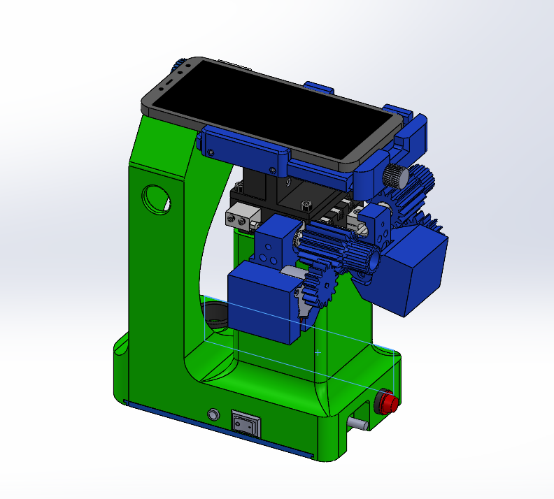
3D printed Frame
The 3D printed frame in SmartScope is designed as a multi-functional
structural platform that integrates mechanical, optical, and electronic
subsystems into a single, compact unit. It serves not only as a
support structure but as a precision alignment and integration architecture.
Aperture Provision for Slide (Optical Interface Zone)
The optical interface zone is the region where the sample slide is
positioned, approximately 120 mm above the illumination source, to
ensure uniform and near-parallel light transmission. This zone is
located directly beneath the spherical lens assembly attached to the
smartphone, forming a critical part of the optical path.
The slide is securely held in place using a bolt-tightening mechanism
integrated near the optical interface. This ensures stability during
observation and prevents unwanted movement that could affect image quality.
Functions:
- Provides a guided sliding mechanism that allows controlled to-and-fro
movement of the sample for precise positioning and alignment under the lens.
- Maintains a consistent and aligned optical path, enabling effective
transmission of light from the illuminator to the specimen.
- Ensures uniform illumination, which is essential for achieving
clear and high-contrast microscopic images.
Precision 3D XYZ Linear Micrometer Mounting
The frame incorporates dedicated mounting holes and peripheral locating features
within its main body to securely accommodate the Precision 3D XYZ Linear
Micrometer. This mounting interface is positioned just above the battery
compartment, ensuring optimal integration without interfering with other
subsystems.
The inclusion of locator features (such as alignment bosses or guide surfaces)
ensures accurate placement of the micrometer assembly, minimizing misalignment
during installation and operation.
Functions:
- Ensures orthogonality of the X, Y, and Z axes with respect to the smartphone
camera and the sample slide, enabling precise orientation and accurate positioning.
- Provides a stable and rigid mounting interface, reducing vibrations and
mechanical errors during operation.
- Transforms the frame from a simple structural support into a precision
positioning system, enabling controlled and repeatable motion of the sample.
Illuminator Provision (Lighting System Integration)
The frame includes a dedicated cutout section designed to accommodate the
illumination system. This provision ensures proper placement and alignment of
the light source directly beneath the optical interface zone, enabling effective
illumination of the sample.
The design also incorporates internal pathways for routing electrical connections,
allowing seamless integration of the lighting system within the structure.
Functions:
- Ensures uniform and consistent light distribution across the sample, which is
essential for clear and high-contrast imaging.
- Maintains proper alignment of the light source, facilitating near-parallel
light transmission toward the specimen.
- Provides integrated wiring channels, enabling safe and organized routing
of electrical connections within the frame.
Electronics Subsystem Provision
The frame incorporates a dedicated cutout at the base to house the
electronics subsystem, including the battery pack and Battery Management
System (BMS). This compartment is designed to securely enclose and
protect the electronic components while maintaining accessibility for
assembly and maintenance.
The layout ensures proper segregation of electrical components from the
optical and mechanical systems, contributing to overall system reliability
and safety.
Functions:
- Provides dedicated mounting points for the PCB, ensuring stable placement
and minimizing the effects of vibration during operation.
- Incorporates cable management pathways, allowing organized routing of
wires and reducing the risk of interference or damage.
- Houses the battery pack and BMS module, enabling efficient power
management, including charging, discharging, and protection.
Precision 3D XYZ Linear Micrometer
Battery Pack
Motorized Coupling
Electronic subsystem
Design & Development
The key components of the mobile microscope included: